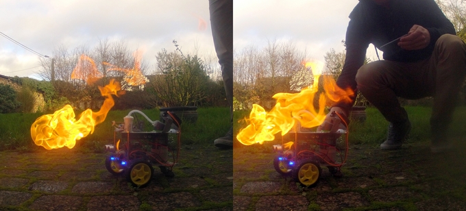
I present my new robot: a flamethrower! This is a robot that is not very difficult to construct and does not require much expertise in electronics. I’ll try to be as clear as possible in my explanations. It is not very expensive and I think all the parts can be obtained for $15.
The robot, including the code, is not complete yet, but it is functional at the moment. I intend to publish one or two updates but feel free to improvise and experiment with the project yourself.
I am a young student (19 years old) in engineering in Belgium. I do not speak English very well so I hope you understand my explanation. Thank you for reading, and please realize that I am willing to answer your questions. I am open to suggestions for improvement as well.
See it on Instructables ?
CAUTION : Don’t use this indoors, or around animals or small children. Please be aware of your surroundings, and keep a fire extinguisher on hand.
Components and tools
The list of all you need :
Electronic components :
- Arduino Nano
- L293D Motor Driver
- Bluetooth Transceiver Module HC-06
- Prototype Paper PCB
- 2 x Smart Car DC Motor 3-6V
- 2 x Blue LED 5mm
- TIP120 (work with TIP31)
- Servo TowerPro SG5010
- MicroServo TowerPro SG90
- HC-SR04 UltraSonic Ranging Sensor
- 2 x 9V Batteries
- 4 x 1.5V Batteries + Support
- 9V battery snap on clip connector
- 3 x Slide switch
- 2 x 1k resistance
- 1 x 2.2k resistance
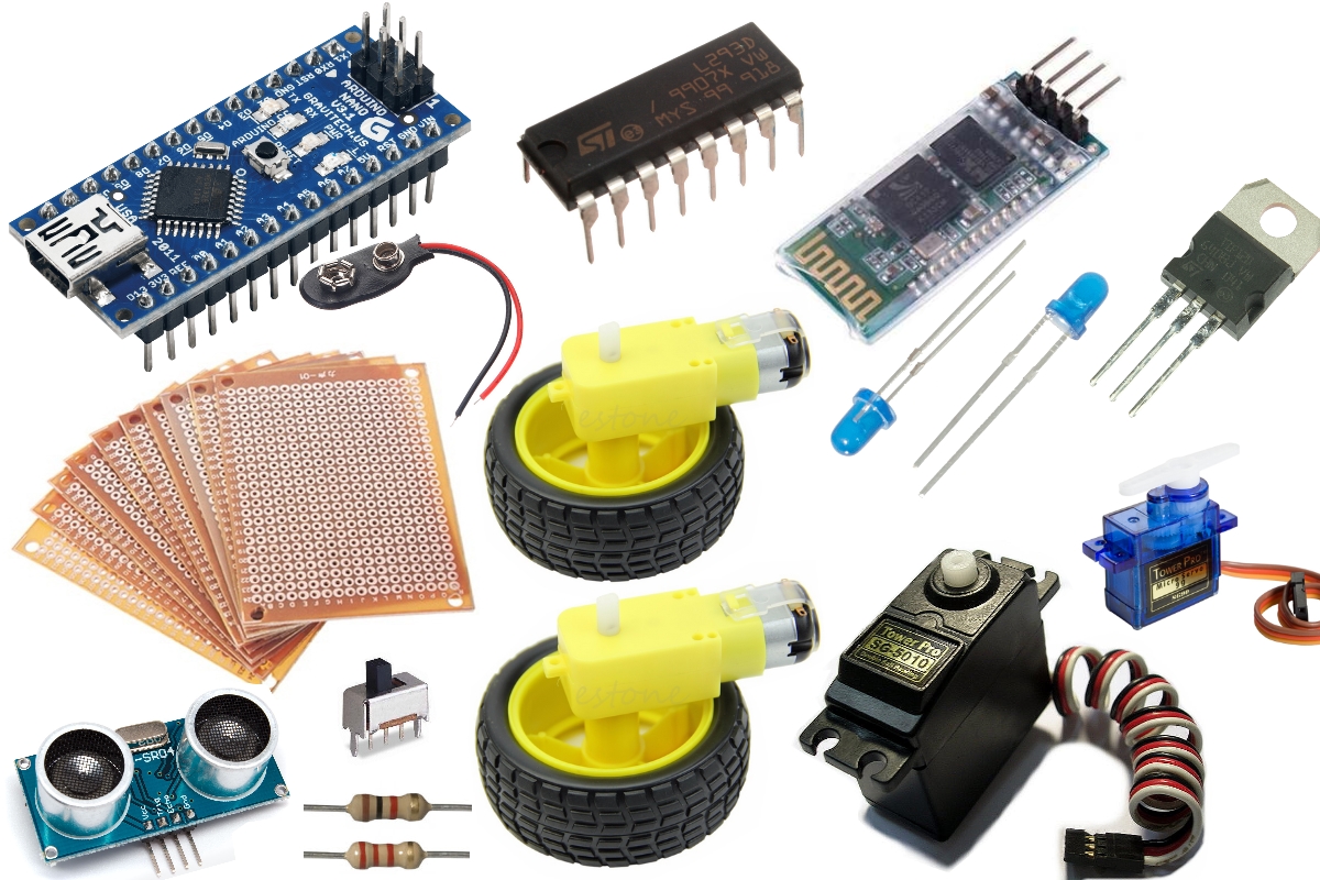
From the shop :
- Brass pipe ( x mm diam)
- Steel sheet ( x mm thick)
- Screws, bolts and washers M3
- Threaded rod M3
- Epoxy Resin
- Rivets
- Large electric tape
- Electric gaz lighter
- Trolley wheel
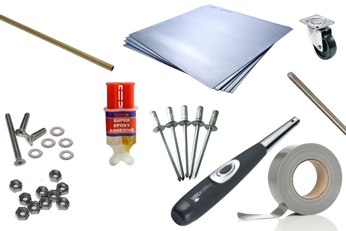
From your bathroom :
- Deodorant pocket size
- Cylindrical box medicine

Tools :
- Soldering iron with tin
- Metal shear
- Drilling machine + metal drill bit
- Riveter
- Pliers
- Screwdrivers
- Cutter
- Sand down paper
- Metal saw
The circuit
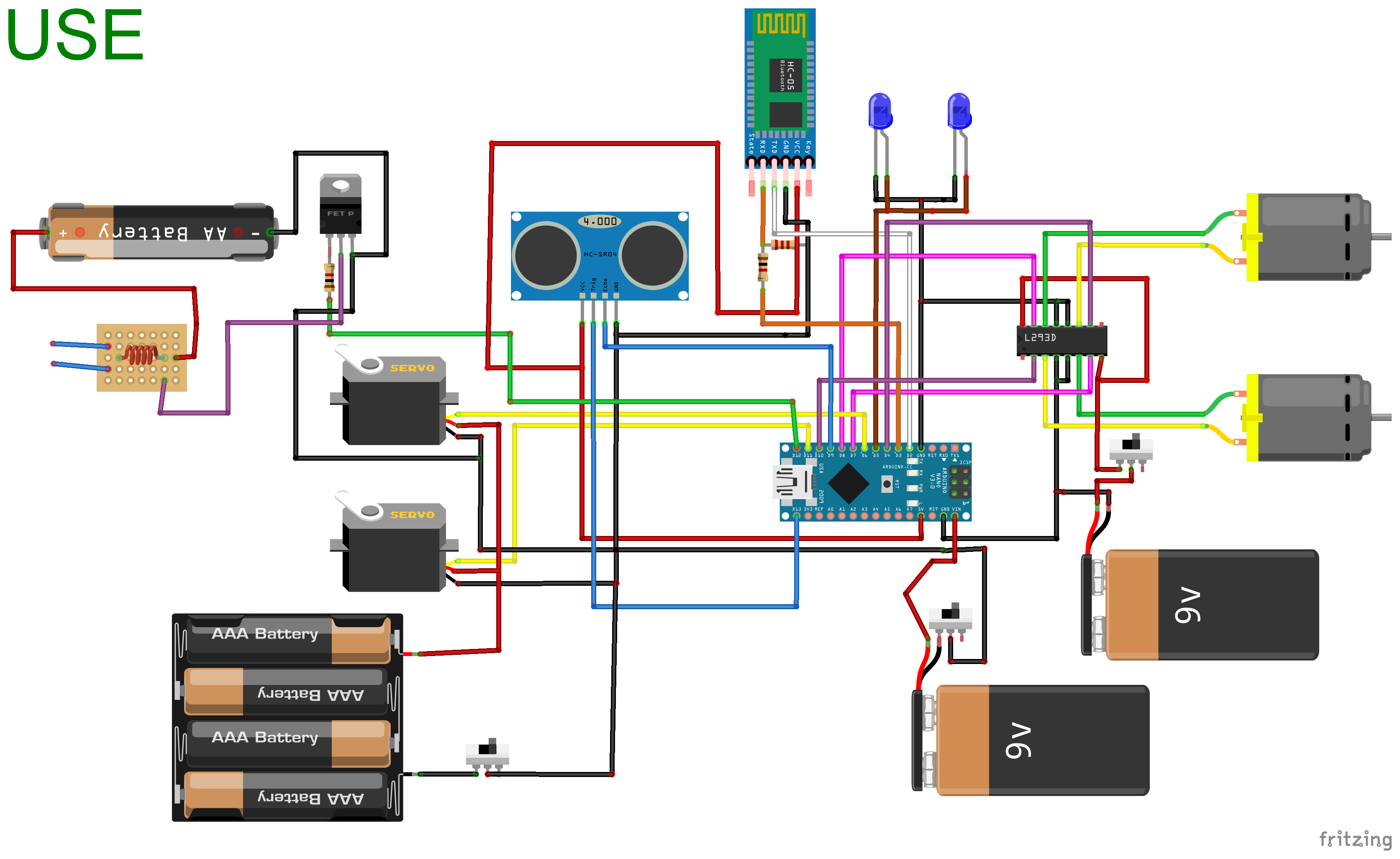
I designed the circuit with Fritzing twice. The first one (in red NOT USE) was the theoretical circuit, in reality, it can’t work because the servo-motors were consuming too much current so the Arduino rebooted. The second circuit (in green USE) was designed on the ground by successive modifications. It works now fine but I do not guarantee that it is technically correct !
We have one servo to trigger the deodorant and the other to rotate the ultrasonic sensor. The bluetooth transceiver is not connected as conventionally (on Arduino TX and RX) because it prevents debug the code easily. You can change that if you want.
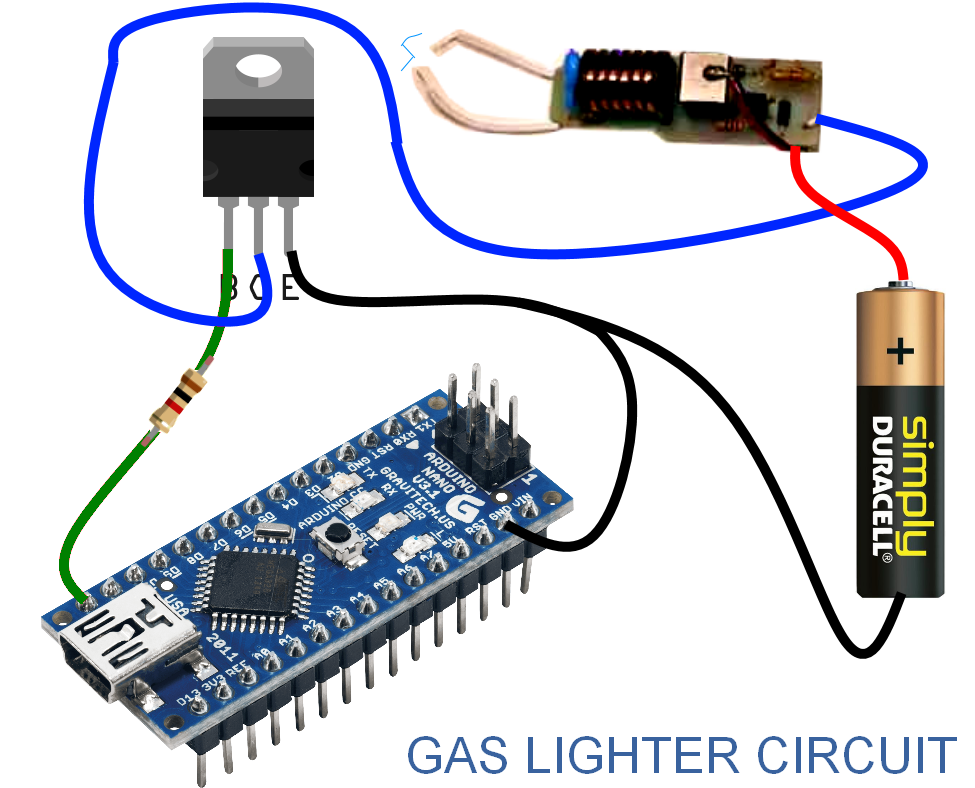
Notice that in the first circuit, the servo trigger was pushing a switch, this last closed the gas lighter circuit : coordination wasn’t obvious… I put a TIP31C (I hadn’t some TIP120) through a 1k resistance and it work fine, the Arduino now can control the electric arc directly.
It’s time to try it on a breadboard to check that all works fine.
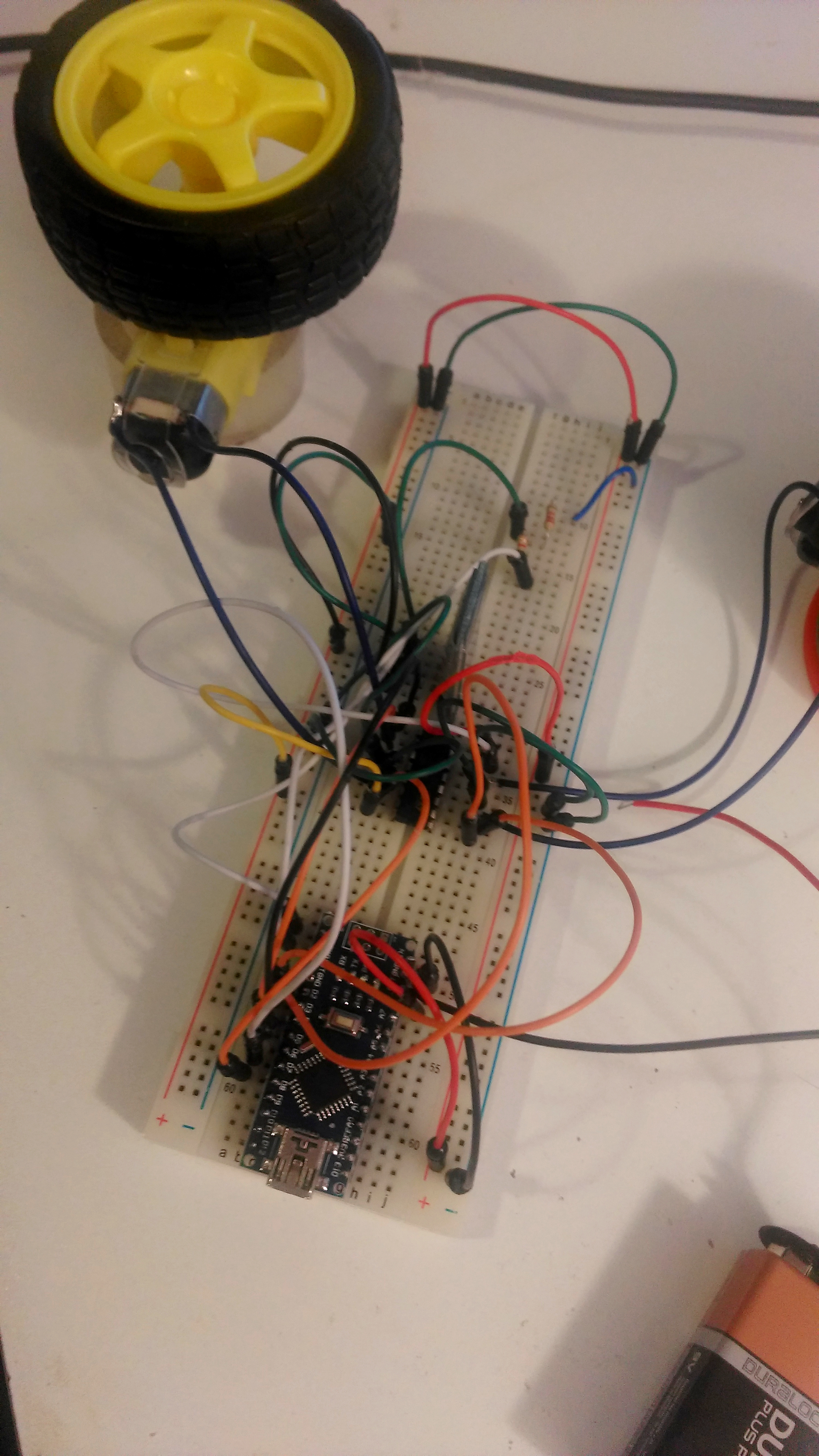
Solder all on the PCB
I decided to divide the whole circuit in 2 board : one for the L293D and the other for the Arduino.
- Build the L293D board to drive motors :
You can see on the first scheme how I dispose components on the PCB. It’s just a suggestion, you aren’t forced to do that. I also use screw terminal connectors to plug easily the twos motors. The scheme show a 3-wires plug but it’s only 2. You can see on the second picture my circuit : it’s very easy to do.
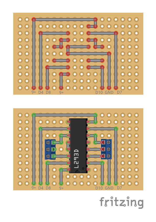
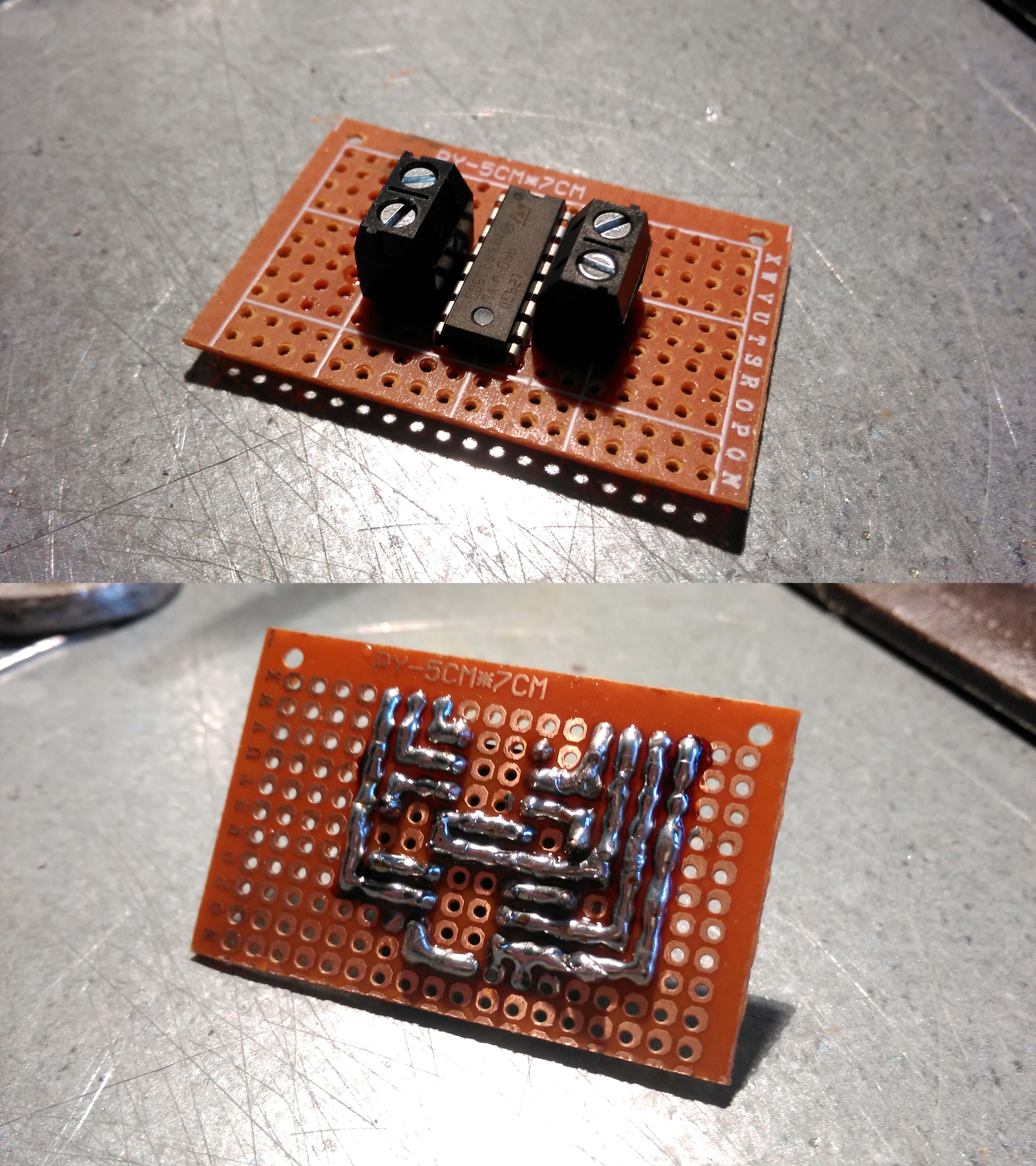
2. Build the Arduino board :
You can see on the third picture the scheme that I designed. The right and left board are the same, it’s just a differente face. Notice that we need 2 wires on the bottom face to plug GND to the rotate sensor servo and to connect the servo 5V alimentation. On the top face, we have a lot of output wire :
- 4 on the left to connect the ultrasonic sensor.
- 1 on the top-left is the signal for the TIP120.
- 4 on the top-center to connect to the L293D board and driving motors.
- 1 on the top-left is the GND of the circuit and it’s used everywhere.
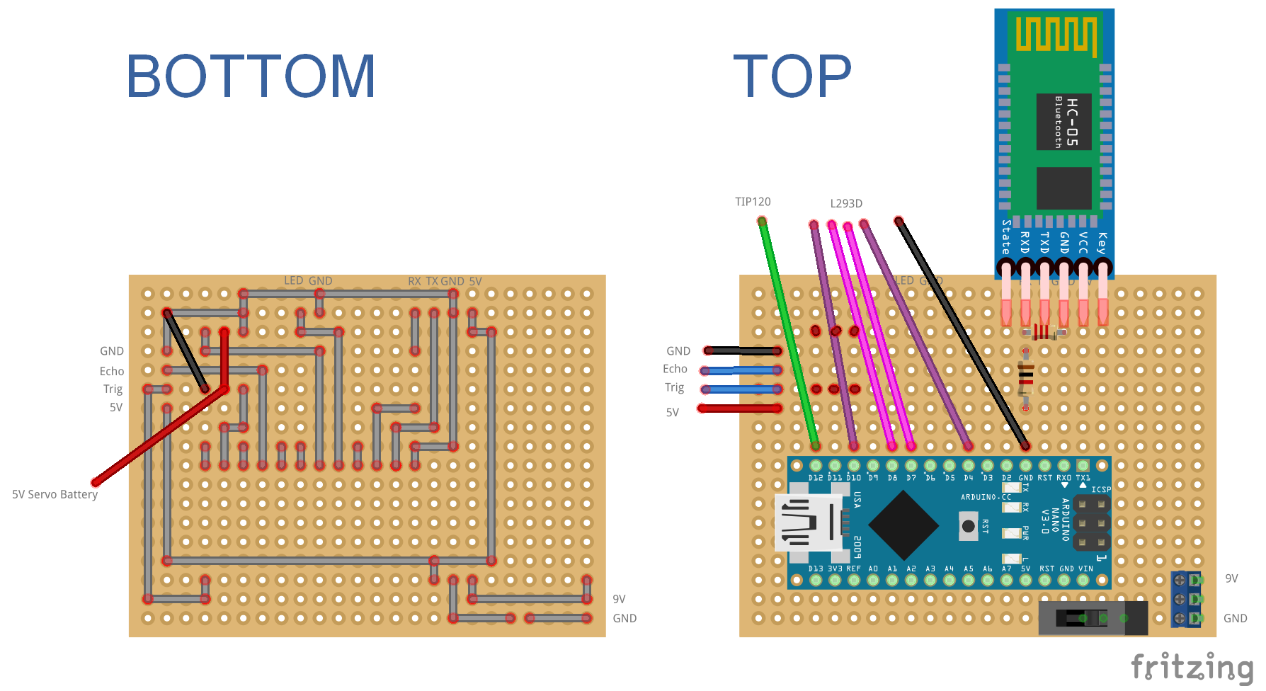
I used 2×3 pins connectors for the two servo-motors and a screw therminal for the Vin.
You can all solder together. Don’t forget to wire together all the GND, a 9V in to the L293D board, 5V in to the servo. Check the last pic, it’s very easy to connect the gas lighter circuit to the TIP120.
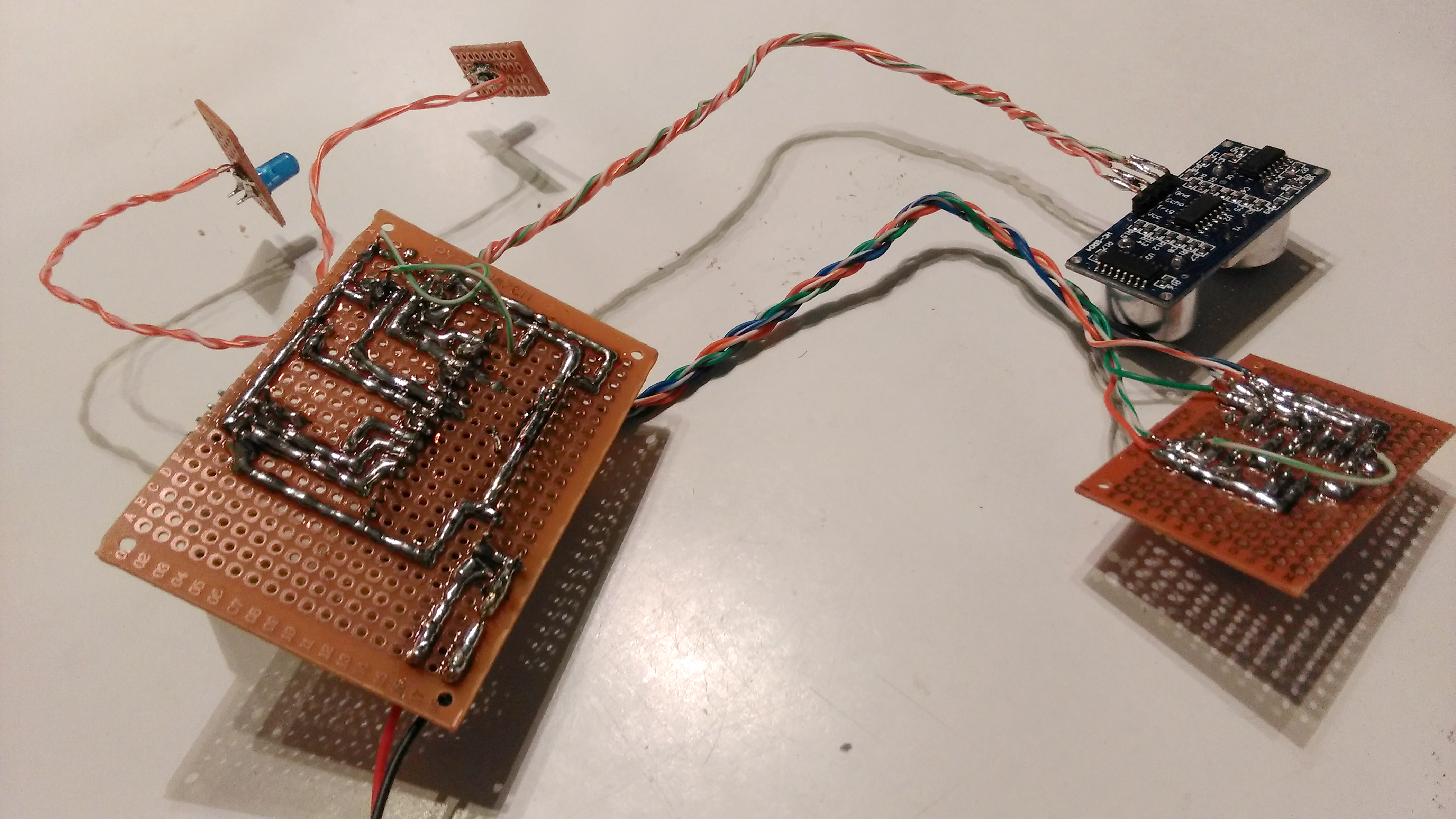
Notice that on my circuit (pics 3, 4), missing some part of the circuit (5V, 2x9V, TIP120 + Lighter circuit and servos)
Build the chassis
The chassis is not complicated to do but it takes so time to build.
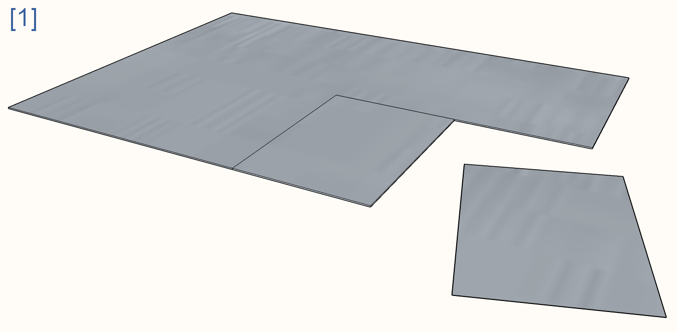
- Cut in the steel sheet 2 pieces of 15x11cm. Use the metal shear to do that step.
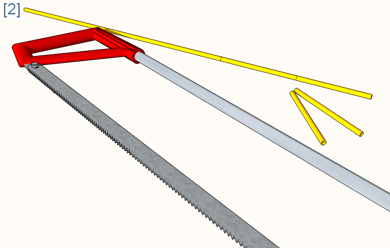
- Cut in the brass pipe 4 pieces of 8.5cm length. We use them to make a rigid structure and easily removable. Also cut 2 pieces of 2cm length. Notice that 8.5 cm is the height of the deodorant behind the valve. You can undertsand why seeing the picture on the intro.
- Cut in the threaded rod 4 pieces of 12 cm length. A little bit more than the brass pipe so we can put some bolts.
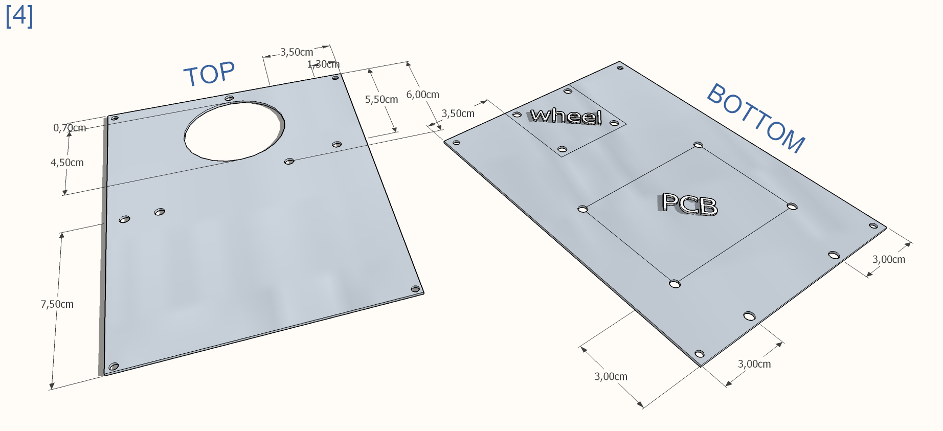
- Take you drill and makes all the holes in the steel sheet ! Use your parts (deodorant, PCB, trolley wheel) to mark the holes. These measures are only a example. You can make the deodorant’s hole with the metal shear.
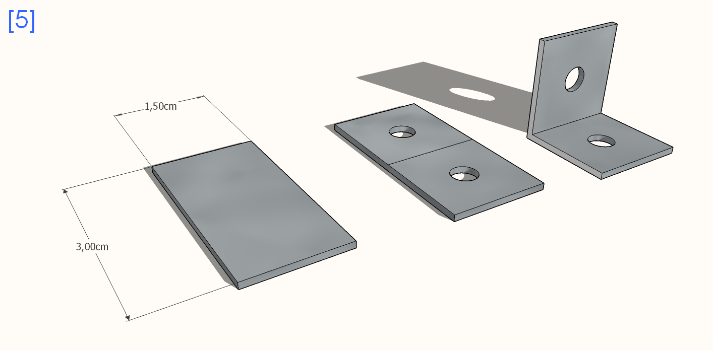
- Cut in the steel sheet 3 pieces of 1,5x3cm. Make holes like on the picture and fold the piece in 2 same part. Those pieces make a solid support for the lights and for the tip31.
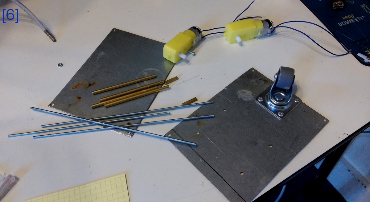
- Rivets the trolley wheel. The differents parts look like the 6 pics.
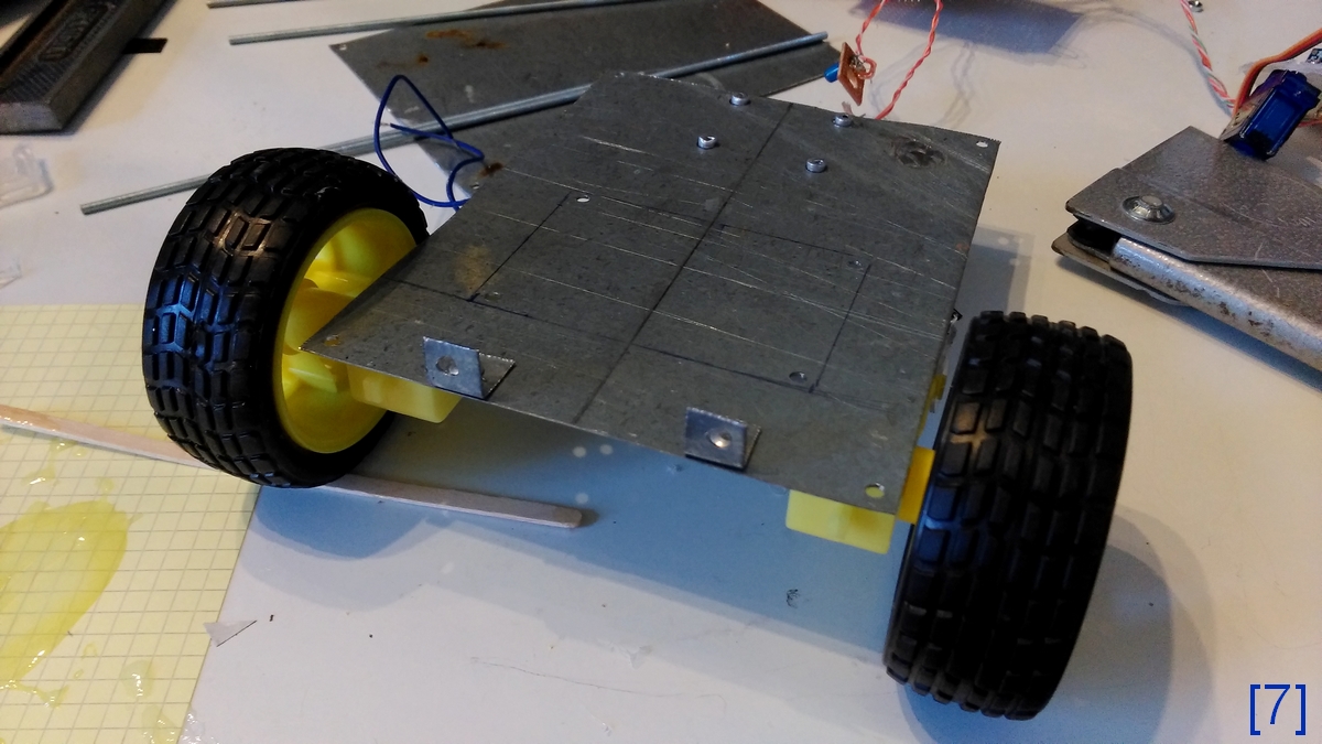
- Sand down the surface of the motors to give them more grip. Glue them with some epoxy directly to the sheet. It’s a difficult step. Pay attention to alignment. You can rivet all suport maked at step 5.
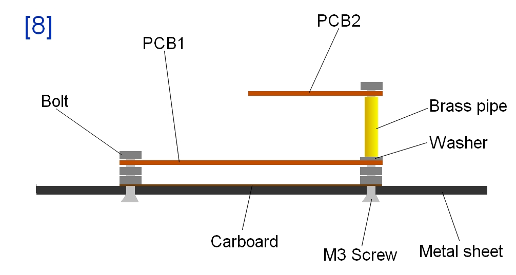
All pieces fit together now. I advice to put some cardboard between the PCB and the metal sheet. Personnaly I cut a PCB size carboard and wrap with some tape. No short-circuit like this. I do the same thing for the gas ligter circuit. The two little piece of brass pipe is used to make a two-floor pcb support, see pic 8.
Build the conduit/non-return flame
- Cut the medicine box half height and glue it with epoxy on the board. The bonding must be waterproof. Drill a hole for a little piece of brass pipe. It will be the fire gun.
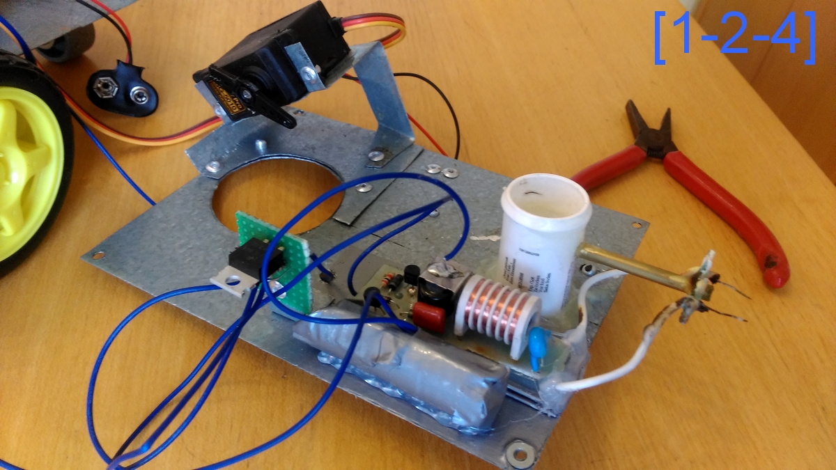
- Rivet the TIP 120 board and glue the gas lighter circuit. Take care about short circuit, put a lot of tape strip to avoid danger. The two electric wires may be cling near the exit of the gun.
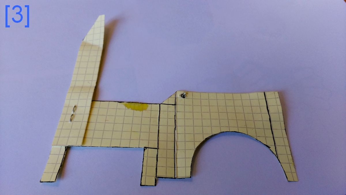
- We will achieve a metal structure for the servo. It should hold up really well. First make a kind of cardboard pattern to try directly with the servo and deodorant.
- Cut out then in the metal sheet, fold it right and then rivet it on the board. The servo will be rivet on this structure.
- Cut the top of the deodorant cap and a hole to let the gas output open. Hot glue a plastic pipe to the medicine box plug. This pipe should be as short as possible !
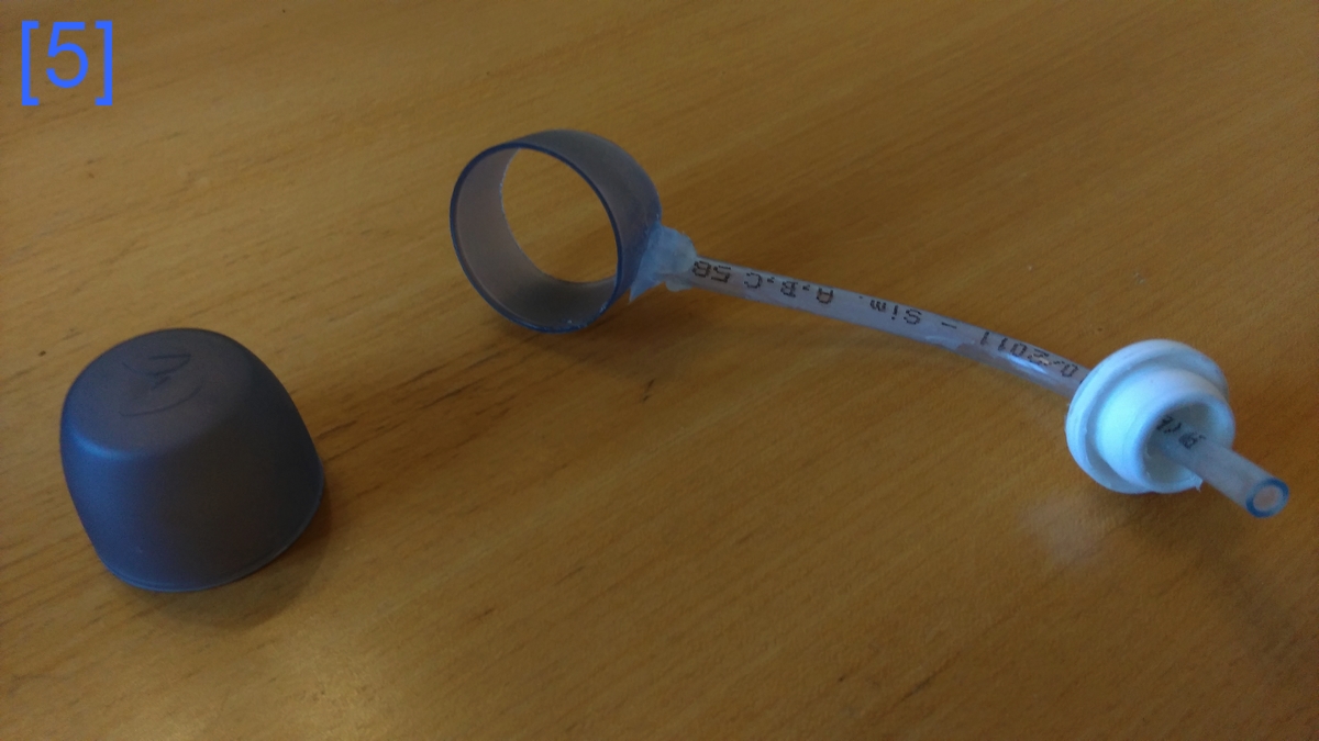
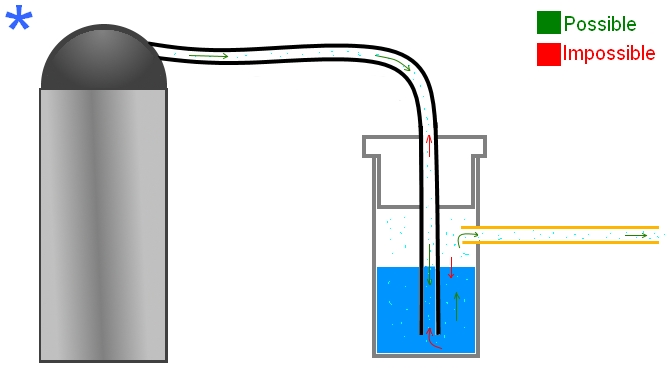
You can plug all together. Fill the medicine box with a little water. The idea is that gas exchange takes place through the water. It will therefore be impossible for the flame across the water and up to explode the carboy (see the * pics).
Upload the code + install the app
- Download the file Robot.ino and upload it to you Arduino Nano. See the instruction on official Arduino web site if you do not know how.
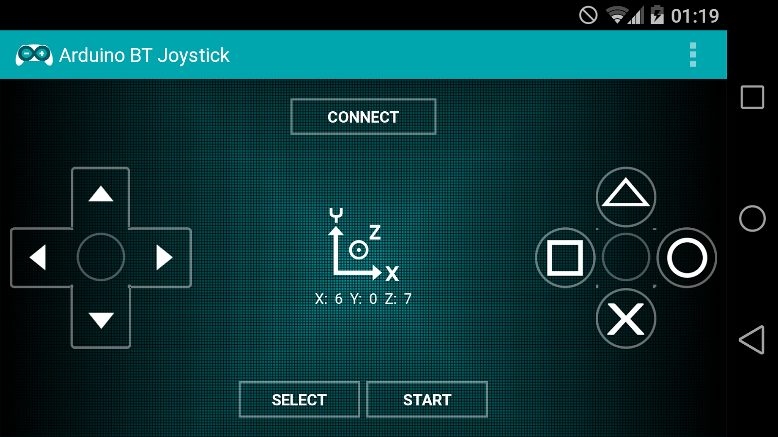
- Take you Android phone and go to the Play Store. Search « Arduino BT Joystick » and install the app. Launch it and turn on the robot. Use the button « connect » connect the phone with the Arduino. You will find « HC-06 » in the bluetooth device list.
- Button :
- Up, Down, Left, Right to manage the movement.
- Triangle to switch on/off the lights.
- Square to launch the flame thower.
- X to blink the lights.
I recall that the code is not finished at all and many improvements are possible.
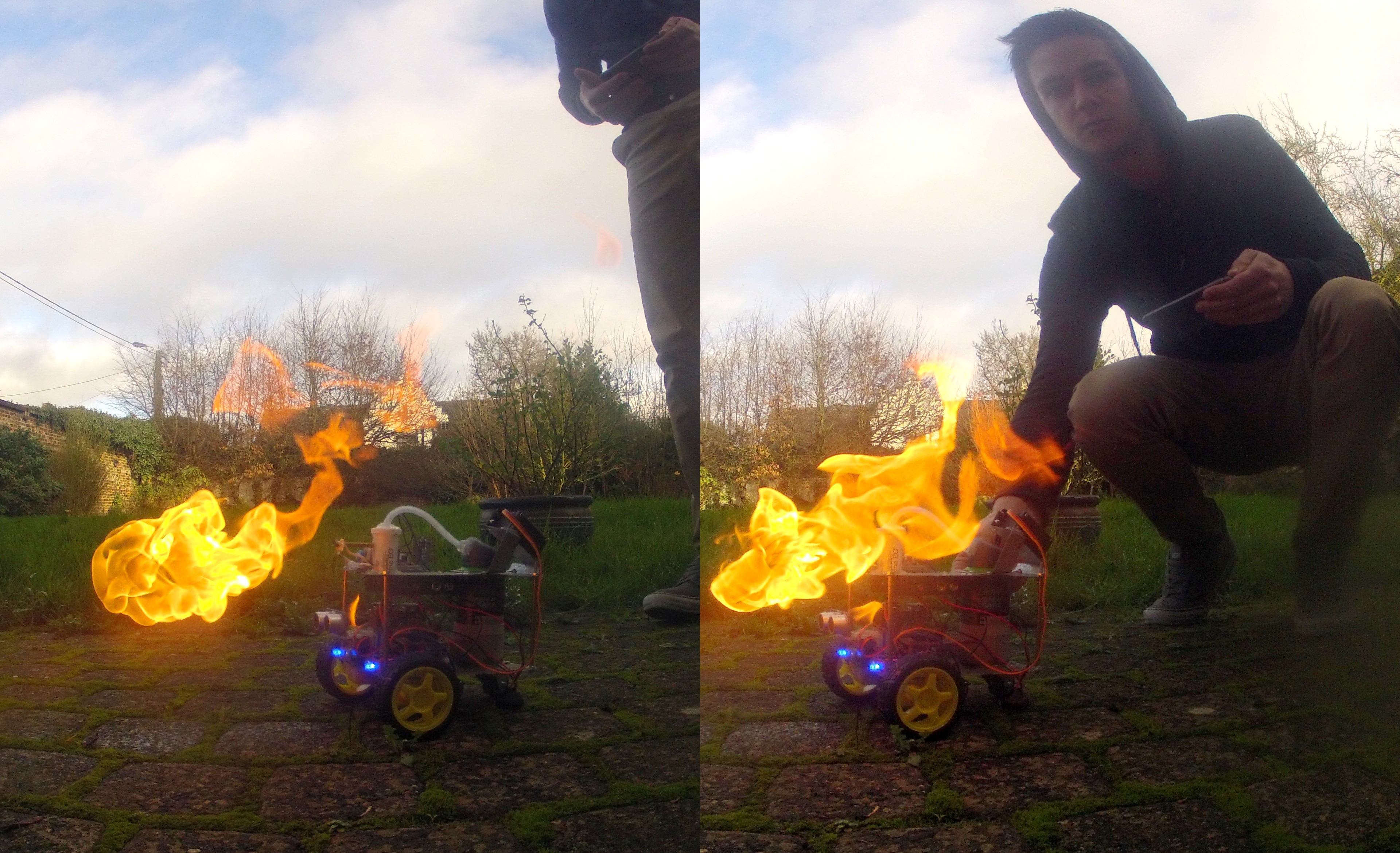
Robot in action :
